Jumat, 15 Juli 2011

RMON


RMON are the functions that monitor the network performance, errors and other summary information. RMON functions can be implemented in a network device (HUB, LAN switch) or a station (PC, Server).

The Remote Network Monitoring (RMON) specification was created. RMON is often called a protocol, and you will sometimes see SNMP and RMON referred to as “the TCP/IP network management protocols”. However, RMON really isn't a separate protocol at all—it defines no protocol operations. RMON is in fact part of SNMP, and the RMON specification is simply a management information base (MIB) module that defines a particular set of MIB objects for use by network monitoring probes. Architecturally, it is just one of the many MIB modules that comprise the SNMP Framework.

RMON (Remote Network Monitoring) provides standard information that a network administrator can use to monitor, analyze, and troubleshoot a group of distributed local area networks (LANs) and interconnecting T-1/E-1 and T-2/E-3 lines from a central site. RMON specifically defines the information that any network monitoring system will be able to provide. It's specified as part of the Management Information Base (MIB ) in Request for Comments 1757 as an extension of the Simple Network Management Protocol (SNMP). The latest level is RMON Version 2 (sometimes referred to as "RMON 2" or "RMON2").

RMON can be supported by hardware monitoring devices (known as "probes") or through software or some combination. For example, Cisco's line of LAN switches includes software in each switch that can trap information as traffic flows through and record it in its MIB. A software agent can gather the information for presentation to the network administrator with a graphical user interface. A number of vendors provide products with various kinds of RMON support.

RMON collects nine kinds of information, including packets sent, bytes sent, packets dropped, statistics by host, by conversations between two sets of addresses, and certain kinds of events that have occurred. A network administrator can find out how much bandwidth or traffic each user is imposing on the network and what Web sites are being accessed. Alarms can be set in order to be aware of impending problems.
READ MORE - RMON
READ MORE - RMON

Kamis, 14 Juli 2011

ACEs


Access control in its basic definition can be anything from scanning your work badge for permit into your employment facility to the old fashion way of handing in a movie ticket for theatre access. It’s the idea and process by which people are identified and granted certain access and in most cases privileges.

Furthermore, computerized access control systems can be security devices that monitor and control entry to a house, apartment, or building. Because keys are easily duplicated, these systems are the best way to keep track of who is entering the area.

When it comes to your business, access control can be designed to restrict access to your building complex in order to increase security and control. There are now access control systems that do away with keys all together and provide computerized trails of who and when someone enters your property.

Access control devices can range from simple electronic keypads that secure a single door to large networked security systems for multiple buildings that can include parking lot gates, integration with time and attendance systems, exit controls, telephone entry, and multiple other levels of security. If a business owner implements sophisticated access control, there should be no need to replace lost keys, track down keys from terminated employees, or wonder who has access to which areas.

If you are seriously considering applying electronic access control devices within your business then know that the local and state law likely will require certain standards which will cost you time and money.

Access control is also important when it comes to work computers and programs, as well as personal computers. Any computer that is networked to any outside source is vulnerable. That is why you can now guard computer and program access with passwords, fingerprint identification, and even more means such as voice recognition or even retinal scans.

Meanwhile, access control from a homeowner’s point of view does not have to be costly and can help prevent unauthorized access onto your property and uphold safety once inside. Such access control devices can be applied to locksets, entry and exit control, even TV and computer privileges.

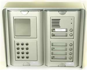
One of the most common access control devices found in the residential area is an electronic entry gate. Even if you have fencing around your home, you should consider installing a security gate in which people must enter an access code in order to gain entry into your driveway and into your home

ACLs can be used to filter traffic for various purposes including security, monitoring, route selection, and network address translation. ACLs are comprised of one or more Access Control Entries (ACEs). Each ACE is an individual line within an ACL.

ACLs on a Cisco ASA Security Appliance (or a PIX firewall running software version 7.x or later) are similar to those on a Cisco router, but not identical. Firewalls use real subnet masks instead of the inverted mask used on a router. ACLs on a firewall are always named instead of numbered and are assumed to be an extended list.

Access Control Entries (ACEs) provide a mapping of user groups to containers. There are five types of ACEs:
User Explicitly identifies an individual user and overrides any other ACE.
Same company Identifies the host organization. This ACE, called People in my company in the Communicator user interface, typically resides in the Company Container. By default, every user in the organization is a member of the Company Container unless the user is explicitly given membership in another container. For example, in Figure 6 above, roy@contoso.com and carl@contoso.com have Team level access
Domain ACE Identifies all users who are members of a specified SIP domain. This ACE is called people in in the Communicator user interface. As shown in Figure 6 above, msn.com is a member of the Public Container, so every member of the msn.com domain can see the user information that is included in the Public Container.
Federation ACE Identifies all users from partner organizations that are federated with the host organization. This ACE is called people in domains connected to my company in the Communicator user interface. For details about federation, see the Microsoft Office Communications Server 2007 Planning Guide.
Public Internet connectivity (PIC) ACE Identifies all users who belong to supported public IM service providers, which can include the MSN network of Internet services, Yahoo!, and AOL. Public Internet connectivity requires a separate license. This ACE is called people in public domains in the Communicator user interface. For details, see the Microsoft Office Communications Server 2007 Planning Guide.
READ MORE - ACEs
READ MORE - ACEs

RJ45


The wires used for a LAN are mostly those headed by an RJ45 jack, which is similar to the jack plugged into your telephone set, but twice as big. Some Ethernet networks use coaxial cables, but that’s rarer, and present in rather large LANs, which span over areas between buildings. If you want to see what a coaxial cable is like, look at the thick cable that links your TV antenna to your TV set.

Ethernet is by far the most popular LAN protocol used today. It is so popular that if you buy a network card to install on your machine, you will get an Ethernet card, unless you ask for something different, if of course that different protocol is available.

Ethernet has evolved over the years. Today, you can get cheap Ethernet LAN cards with speeds up to 100 Mbps; while the fastest Ethernet reaches Gbps (1 Gbps = 1000 Mbps) in speed.
READ MORE - RJ45
READ MORE - RJ45

Switches


Switches allow us to create a "dedicated road" between individual users (or small groups of users) and their destination (usually a file server). The way they work is by providing many individual ports, each running at 10 Mbps interconnected through a high speed backplane. Each frame, or piece of information, arriving on any port has a Destination Address field which identifies where it is going to. The switch examines each frame's Destination Address field and forwards it only to the port which is attached to the destination device. It does not send it anywhere else. Several of these conversations can go through the switch at one time, effectively multiplying the network's bandwidth by the number of conversations happening at any particular moment.

Another analogy which is useful for understanding how switches increase the speed of a network is to think in terms of plumbing. For sake of argument, assume that every PC on a network is a sink, and a 10 Mb/s connection is a 1/2-inch pipe. Normally, a 1/2-inch pipe will allow enough water to flow for one or two sinks to have enough water pressure to fill quickly. However, putting more sinks on that same 1/2-inch pipe will drop the water pressure enough that eventually the sinks take a very long time to fill.

To allow all sinks to fill quickly, we can connect the source of water to a larger (6-inch) pipe, and then connect each sink to the 6-inch pipe via its own 1/2-inch pipe. This guarantees that all sinks will have enough water pressure to fill quickly. See Figure One for an image of this concept.

Most network operating systems now use a "Client-Server" model. Here, we have many network users, or "clients" accessing a few common resources, or "servers." If we look at our previous highway example, an analogy would be to have a hundred roads for individuals all converging at two or three common points. If these common points are the same width as our individual roads, then they cause a major bottleneck, and the end result is exactly the same as if everyone was sharing one small road. This totally defeats the purpose of building all the individual roads in the first place.

The solution is to widen the road to our shared resource so that it can support the full load of most or all of the individual roads at once. In other words, we increase the bandwidth to our servers while connecting our clients at 10 Mbps. This is usually referred to as a High Speed Backbone. In networking slang, it is commonly called a "Fat Pipe."

This layout is splitting our overall network into four subnetworks. From left to right these subnetworks are outlined in Red, Green, Blue, and Violet. The Red subnetwork is a shared 10 Mbps setup, with all of the "Undemanding Users" sharing 10 Mbps of bandwidth. The Green and Blue subnets are dedicated 10 Mbps connections, sometimes referred to as "Private Ethernets." Here, each of the two power users has 10 Mbps of bandwidth dedicated to his or her machine, and this bandwidth is not shared with anyone else. Finally, we have our Violet subnetwork. This one is a Fast Ethernet setup running at a speed of 100 Mbps, and the bandwidth is shared by the two servers.

This is the most common way of setting up a switched network, and almost always results in an optimal price/performance ratio. We limit the amount of expensive Fast Ethernet hardware needed by only using it where its cost is justified by the performance it gives in handling the load at that point in the network, while leveraging an existing investment in 10 Mbps equipment in less demanding parts of the network. As a 10/100 switch is a fairly costly piece of equipment, each port we dedicate to a user is also rather expensive, so again these are only dedicated to individual users where that user's load justifies it. Finally, we can set up shared subnetworks which lump anywhere from two up to 100 users on one switch port.
READ MORE - Switches

DCE


The success of the original Ethernet project lead to a joint development of a 10 Mbps standard in 1980. This time three companies were involved: Digital Equipment Corporation, Intel and Xerox. The Ethernet Version 1 specification that arose from this development formed the basis for the first IEEE 802.3 standard that was approved in 1983, and finally published as an official standard in 1985. Since these first standards were written and approved, a number of revisions have been undertaken to update the Ethernet standard and keep it in line with the latest technologies that are becoming available.

Ethernet standard releases

The Ethernet standard has undergone many releases and updates as a result of the continual development of the technology. In this way, Ethernet has been able to meet the ongoing needs of the industry.

Ethernet terminology

There is a convention for describing the different forms of Ethernet. For example 10Base-T and 100Base-T are widely seen in the technical articles and literature. The designator consists of a three parts:
The first number (typically one of 10, 100, or 1000) indicates the transmission speed in megabits per second.

The second term indicates transmission type: BASE = baseband; BROAD = broadband.

The last number indicates segment length. A 5 means a 500-meter (500-m) segment length from original Thicknet. In the more recent versions of the IEEE 802.3 standard, letters replace numbers. For example, in 10BASE-T, the T means unshielded twisted-pair cables. Further numbers indicate the number of twisted pairs available. For example in 100BASE-T4, the T4 indicates four twisted pairs.


Elements

The Ethernet LAN can be considered to consist of two main elements: the interconnecting media, and the network nodes.

The network nodes themselves fall into two categories. The first is the Data Terminal Equipment (DTE). These devices are either the source or destination of the data being sent. Devices such as PCs, file servers, print servers and the like fall into this category. The second category of devices are known as Data Communications Equipment (DCE). Devices that fall into this category receive and forward the data frames across the network, and they may often be referred to as 'Intermediate Network Devices' or Intermediate Nodes. They include items such as repeaters, routers, switches or even modems and other communications interface units.

The media through which the signals propagate are just as important. Initially coaxial cable with a single inner connector were used. Now either an Unshielded Twisted Pair (UTP) or a Shielded Twisted Pair (STP) are normally used. There are also optical fibre options, and these are often used for the much higher data rate systems.

Network topologies

There are several network topologies that can be used for Ethernet communications. The actual form used will depend upon the requirements.

Point to point - This is the simplest configuration as only two network units are used. It may be a DTE to DTE, DTE to DCE, or even a DCE to DCE. In this simple structure the cable is known as the network link. Links of this nature are used to transport data from one place to another and where it is convenient to use Ethernet as the transport mechanism.

Coaxial bus - This type of Ethernet network is rarely used these days. The systems used a coaxial cable where the network units were located along the length of the cable. The segment lengths were limited to a maximum of 500 metres, and it was possible to place up to 1024 DTEs along its length. This form of network is not used these days, although a very few legacy systems might just still be in use.

Star network - This type of Ethernet network has been the dominant topology since the early 1990s. It consists of a central network unit, which may be what is termed a multiport repeater or hub, or a network switch. All the connections to other nodes radiate out from this and are point to point links.
READ MORE - DCE
READ MORE - DCE

STP


Most of the electronics devices we use, such as personal computers and laptops, communicate by sending each other Ethernet packets. They are notated as Ethernet stations. Each such station has a unique address (a globally unique number comprises of 48 bits). This is called a MAC address. Each station has a network interface card (NIC) which is aware of this number and would not let an Ethernet packet with another MAC address to enter the station itself. Also, this MAC address is added to any packet transmitted from this NIC. Eventually, any packet carries the unique source address along its way.

The main component in an Ethernet network is the Ethernet switch (For clarity we discuss here Switched Ethernet, and ignore an older Shared Ethernet scheme, which is almost obsolete). A switch is connected to the stations either by a copper cable or a fiber cable, and can connect to various speed stations. Since all the stations, regardless of the speed itself use the same packet format, the switch enables all stations, regardless of their speed to interconnect.

As defined by the IEEE 802.3 group, the Ethernet switch is designed to detect the Ethernet packet origin (Ethernet Source Address) and the packet destination (Ethernet Destination Address). The destination and the source addresses are the first parameters in an Ethernet packet, and are read by the switch. A table of addresses within the switch constantly learns and keeps records of the addresses that are included in the packets entering the switch over the time, and organizes the address table such that each address is related to the port from which certain source address entered the switch. This table is served to direct each incoming packet to its relevant output port, so that the packet should reach its destination eventually.

The detection of the addresses, learning the addresses, and the decision where to switch the packet to, are all done by hardware means, as fast as possible. This is why Ethernet can reach 100Gbits/second.

The IEEE 802.3 definition of Ethernet includes, of course, some more notions such as Full-Duplex, Flow Control, Cut-Through, Store-and-Forward, MAC, Broadcast and Unicast packets, Auto-negotiation, Spanning Tree (STP), and more. We will discuss these topics in further articles.
READ MORE - STP
READ MORE - STP

IEEE 802.3


During the 90s of last century, many existing protocols and architectures in social networks. Engineers have developed several types of protocols, each for a specific use of disclosure of information such as the transfer of data, voice, broadcasting, data center, and so on. Among them can be found Token Ring, FDDI, ATM and more.

However, due to the simplicity and low cost of Ethernet components, it has prevailed in the end, and is now the most widely used protocol in local area networks (LAN). Faster Ethernet protocol have been defined that can fit many of the above applications and network.

In reality, Ethernet is a family of protocols, each with a different speed, and all are based on packet transfer, as defined by IEEE 802.3 standards group. Today there are Ethernet protocols and components ranging from 10Mbit/sec (10 million bits per second), a 100Mbit/sec (aka Fast Ethernet), 1 Gbit / sec (1 billion bits per second), 10Gbit/sec, 40Gbit / sec and recently 100Gbit/sec.

Ethernet is a protocol physical layer (layer1 and 2 of the 7 levels of the OSI model). It defines the way in which an Ethernet frame (packet) is transferred to the cable / fiber, Ethernet switch and how long the path may lead the structure to its destination.

Ethernet can run on twisted pair copper cables and fiber cables. Copper cables, usually able to transfer Ethernet packets up to 100 meters, and are mainly used in the creation of internal networks. The fiber can reach tens of kilometers and are used to interconnect between campus and down town.

Being a physical layer protocol, Ethernet is a carrier of data for higher level protocols such as IP (Internet Protocol). In fact, most of the cases in which people discuss the IP protocol, Ethernet protocol assumes discussed as a vector. The IP protocol allows communication between two logically separated networks. That is, Ethernet enables direct communication within a logical network, called the VLAN (Virtual LAN), and you must use the IP protocol to route the packet correctly between the Ethernet VLAN.

Most of electronic devices such as personal computers and laptops, to communicate by sending each Ethernet packet. They are identified as Ethernet stations. Each station has a unique address (a unique number consists of 48 bits total). This is called a MAC address. Each station has a network interface card (NIC) that is aware of this issue and would not let an Ethernet packet with a different MAC address to enter the station. Furthermore, this MAC address is added to any packages sent by this network adapter. In the end, each packet contains the unique address of origin in its path.

The main component of an Ethernet network is the Ethernet switch (For clarity we discuss here Switched Ethernet, and an old pattern of ignoring shared Ethernet, which is almost obsolete). A switch is connected to the remote via a copper wire or fiber cable, and can connect to different stations speed. Since all stations, regardless of the speed using the same packet format, the option is active all stations, regardless of their speed interconnect.

As defined by the IEEE 802.3 group, the Ethernet switch is designed to detect the origin of the Ethernet packets (Ethernet Source Address) and the destination of the packet (Ethernet destination address). The destination and source addresses are the first parameters in an Ethernet packet, and are read by the switch. A table of addresses within the switch is constantly learning and maintaining records of addresses that are included in the packets entering the switch in time, and organizes the address table so that each address is tied to the port from which the source address some joined switch. This table is used to route each incoming packet to its appropriate output port, so that the packet should reach its destination at the end.
READ MORE - IEEE 802.3
.::BY JUMBHO MY AT HOME IN THE JEPARA CITY OF BEAUTIFUL::.